


Hi folks! In 4 days I head to Seeedstudio in Shenzhen where we are going to try to produce a manufacturable Mothbox PCB! The idea behind this PCB is that someone who wants a mothbox can have one by ordering just a couple parts:
- Mothbox PCB (Basically a big pi HAT)
- Pi 5
- Arducam 64mp
- Battery (9-36v)
We are working on the PCB design, but I figured I would also throw some of our ideas in front of you fine folks to get some opinions on the electrical engineering!
You can see a lot more detail about our ideas for this thing here:
Mothbox/Hardware/PCB/mothbox_front-main at main · Digital-Naturalism-Laboratories/Mothbox · GitHub
Developing an open source,low cost automated system for Moth-Lighting photography - Mothbox/Hardware/PCB/mothbox_front-main at main · Digital-Naturalism-Laboratories/Mothbox

but for now, I mainly want some feedback on our overall flow diagram to make sure we aren't goofing on anything obvious!
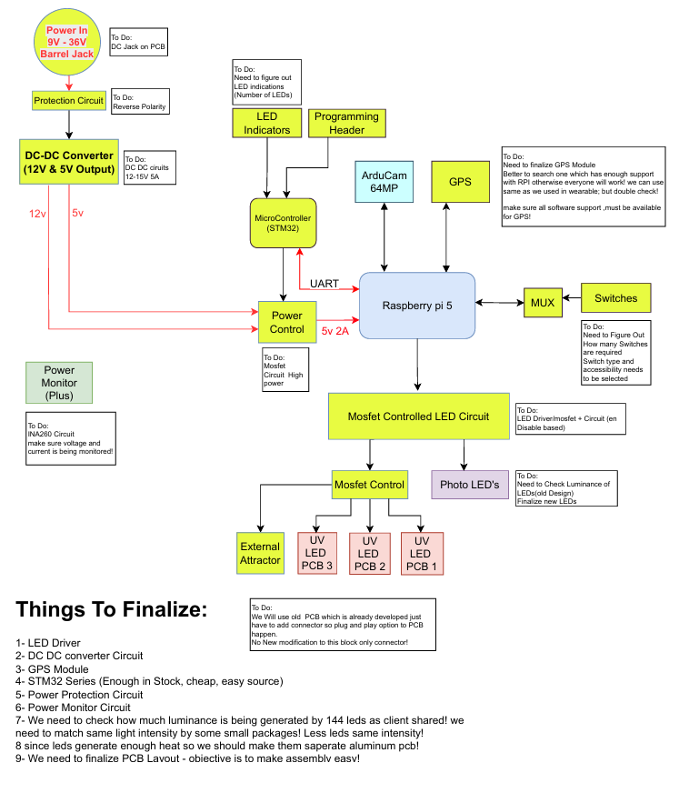
The core idea is that this is a HAT that connects to the PI and the Pi can turn on its photographic lights ( distributed all over the front) along with attractor lights. It also features a bunch of little switches to physically program the mothbox's schedule. There is a bonus STM32 microcontroller (thanks ARM!) we aim to integrate that helps completely cut off the power flow and turns the Pi5 on and off when needed (and uses EXTREMELY little dormant energy compared to the pi5's "off state"). Everything gets power from a set of regulators that take in 9-36V and output 12v5a (and another buck converter for the pi's 5v5a).
notes and questions:
1 - That diagram shows 5v2a going to pi, it should be 5a
2 - Should the "power control circuit" be moved in front of the DC-DC converter? Will the converter use a lot of power even if there is no load? (but then how does the STM get regulated power?)
3- The attractor LEDs are going to be created on a separate PCB (because they get HOT and are on for long times and likely need to be aluminum). These are just going to be Mothbeams which Moritz already designed (
Mothbox/Hardware/PCB/MoritzMothbeamv3 at main · Digital-Naturalism-Laboratories/Mothbox · GitHub
Developing an open source,low cost automated system for Moth-Lighting photography - Mothbox/Hardware/PCB/MoritzMothbeamv3 at main · Digital-Naturalism-Laboratories/Mothbox
)
, but they will be tweaked to be easily connected to the main PCB. Any ideas for good ways to connect PCB to PCB easily?
4- Other things i might be missing?
5 - DC-DC power conversion. So far we have been using these things:
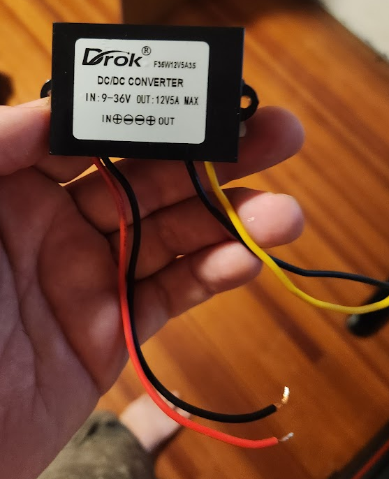
But we have had a decently high rate of failure (e.g. they kinda melt and stop working after a long time in the field)
We upgraded to this slightly more expensive ones (19.99) on the right in this photo that have a big metal heatsink
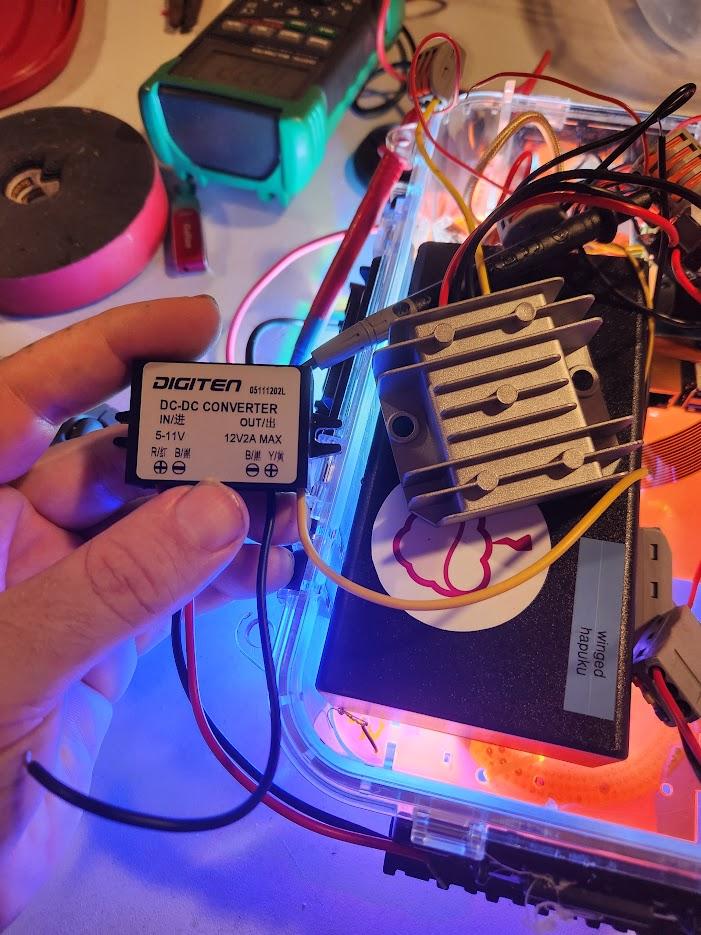
Should we not even try building this part in the PCB? should it just be bought separately and attached?
7 - User feedback
We want a cheap and low cost indicator of the device's state. The main thought is an LED that is normally OFF when disarmed, and then when it is armed, the LED changes from green to Red to indicate it will start its sequence within 12-1 hours. Other ideas for feedback? Would it make sense to try to incorporate a little LCD or even e-ink display? (that could tell us the device name and other things, but is maybe costly/power sucking?)
3 May 2025 7:45am
Nice seeing what you are doing here. Those converters are nice, I’m using them with my portable thermal cameras.
do you have solar power intentions here ? If so, maybe you need a way to detect when the battery is almost out of power?

Kim Hendrikse