
Zoological Society London (ZSL)


Introduction
This article covers the Alpha testing period of ZSL’s Instant Detect 2.0 system from 2021 to 2023 and follows on from Instant Detect 2.0 – The Optimisation Years. Specifically, it provides technical insights into how we tested, optimised and found the limits of the system’s custom LoRa radio network and how we assessed if our metal detecting camera was a more effective tool for threat detection than motion detecting cameras. We hope it will provide useful insights for other conservation technology developers.
The Perfect Alpha Site
Instant Detect 2.0 was incredibly lucky to have the perfect Alpha testing site – ZSL’s Whipsnade Zoo. Here, with the generous assistance of zookeepers and local landowners we were able to deploy the system in a wide variety of set-ups for long durations. An enormous thank you to the keepers at Whipsnade Zoo, with a special mention to the Deer and Antelope team for putting up with all our equipment for so long, as well as Dagnall Farm.
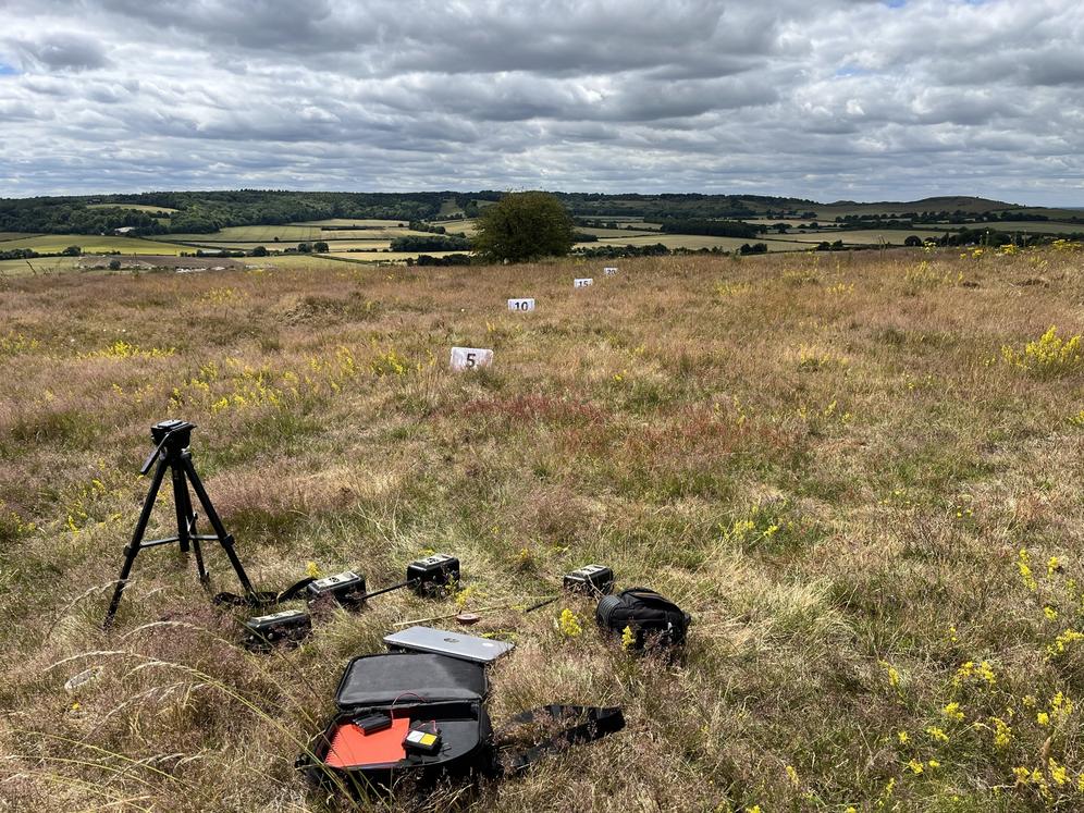
Whipsnade Zoo's deer paddocks provided the perfect undisturbed testing site for Instant Detect 2.0. In this image the focal lengths of different camera lenses are being compared. In the distant background you can see the hedgerows and trees of Dagnall Farm where cameras were later deployed in 2022. Credit: Sam Seccombe
The LoRa Radio Network
Testing at Whipsnade Zoo started in mid-2021, with our initial focus being on the system’s custom low-power long-range (LoRa) radio protocol. This custom LoRa protocol enables multiple cameras and sensor endpoints to transmit images and data reliably over long ranges to the satellite Base Station and means that a single system can provide monitoring coverage over a wide area. For an introduction to this custom LoRa network see - Instant Detect 2.0 Emerges.
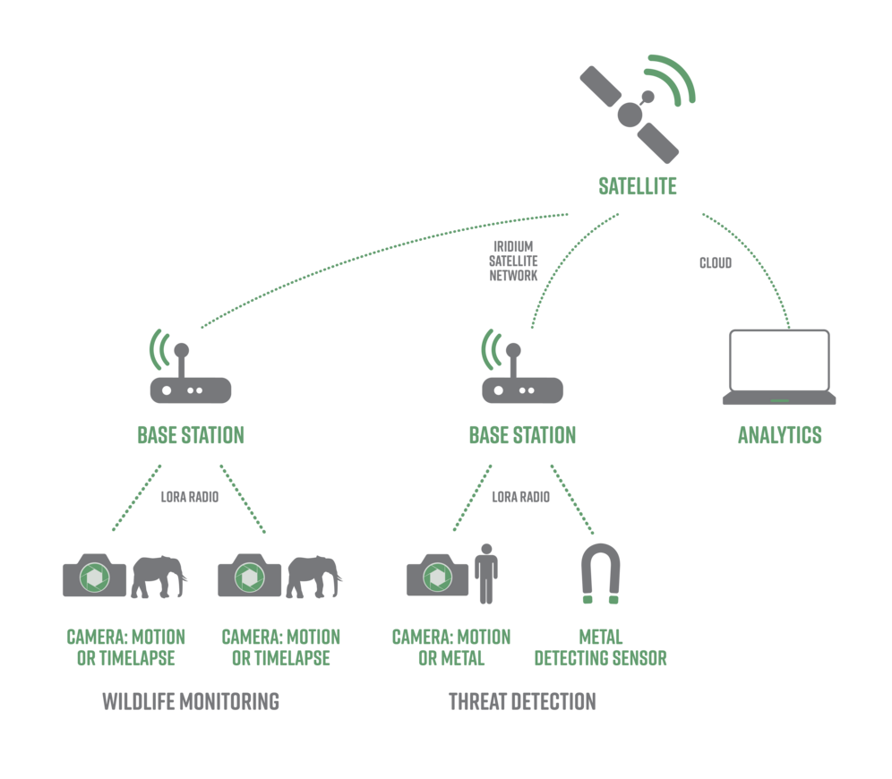
Instant Detect 2.0's network diagram. Credit: ZSL
RF Compliance
To properly appreciate the complexities of developing this protocol, it is important to know that the design has to conform to a number of radio-frequency (RF) emission rules, known as RF compliance for certification. Unless it abides by these rules, the protocol would be illegal.
The purpose of these RF rules is to prevent a single transmitter hogging all the radio airwaves. They do so by dictating the power level, duration and frequencies that an RF device can use. As such, they are also referred to as polite spectrum usage, duty-cycle or airtime restrictions. See my previous article which describes the carnage that could occur without them - Instant Detect 2.0 – The Optimisation Years.
All you really need to know is that for Instant Detect 2.0 to abide by these RF rules, the system’s devices are limited to how long they can transmit on any given frequency.
Sending Images Using LoRa
Sending images using a LoRa radio protocol is very unusual, in fact, it’s almost unheard of. People familiar with LoRaWAN networks will know it’s not possible…
To do it, the Instant Detect 2.0 camera splits an image file into thousands of small data packets and then rapidly sends these packets one by one to the Base Station. The receiving Base Station acknowledges the receipt of every packet with a returned ‘ack’ transmission which lets the camera know to send the next packet.
If the transmission becomes garbled or a packet is missed, the Base Station requests a re-transmission of the missing packet instead of an ‘ack’. In this way, the custom LoRa protocol is very reliable as it ensures nothing ever gets lost in the ether.
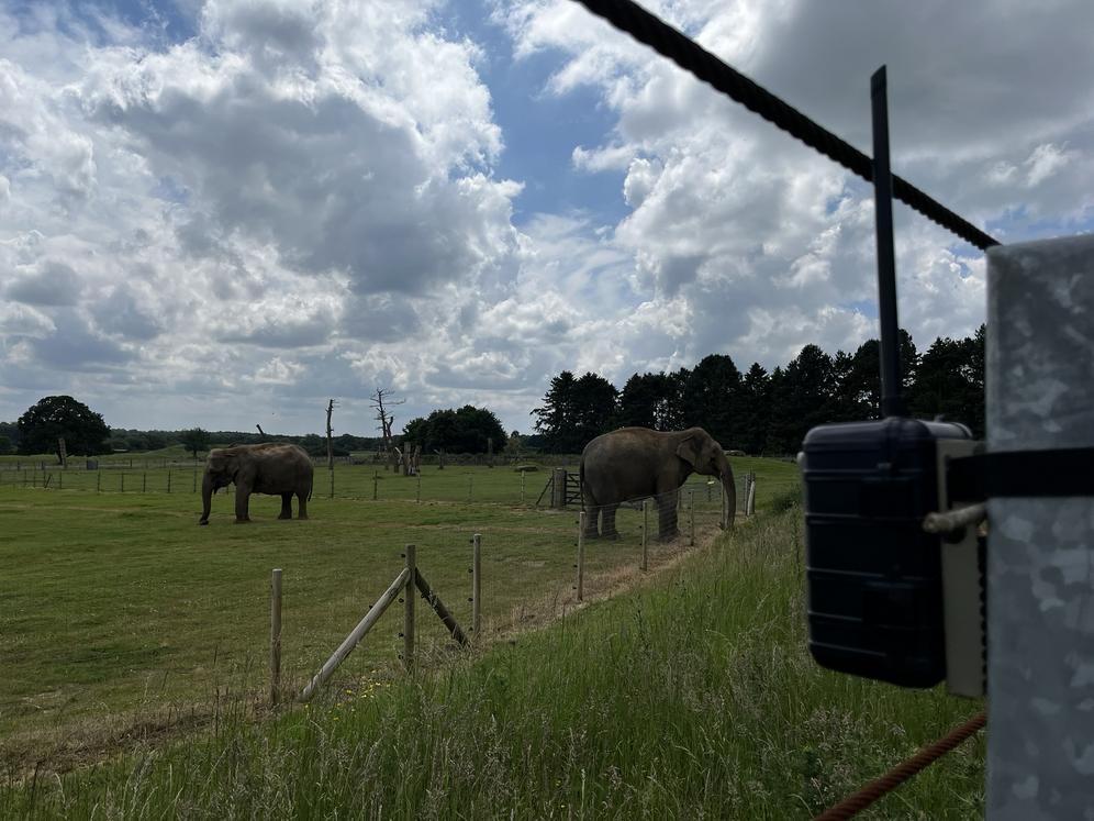
An Instant Detect 2.0 camera monitoring the elephant paddock at Whipsnade Zoo in 2024. Credit: Sam Seccombe
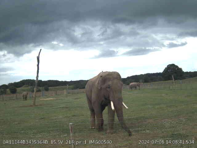
The elephant keepers were able to recognise the individual elephants captured in the images and tag them at Instant Detect Cloud. This is Ming Jung. Credit: Sam Seccombe
Transmission Speeds (Spread Factors)
A special feature of LoRa is the ability to transmit at 6 different speeds, called spread factors (SF). The fastest speed is SF 7 and the slowest is SF 12.
The key thing to know is that for every increase in the SF number, the speed of a transmission will half. So, using SF 8 instead of SF 7 will double the transmission time. This means that if an image transmission was taking 1 minute to send with SF 7, it would take 32 minutes using SF 12!
At this point it’s useful to know that radio signals follow the laws of physics. As such, signal strengths become weaker as the transmission range increases and signal strength will also be reduced when obstructed by vegetation or other radio ‘noise’.
As LoRa radios cannot increase their transmission power, which must remain low, they cannot just shout louder to transmit across longer ranges. Instead, they slow their transmissions using SFs, with SF 12 able to maintain a connection even with an extremely weak signal strength.
The Speed/Range Balance
In the RF Compliance section above we learnt that Instant Detect 2.0 devices are limited to how long they can transmit for, so ideally you would just transmit at the fastest SF 7 speed and maximise our data throughput.
However, we also want Instant Detect 2.0 devices to connect at the longest possible ranges where there is likely to be lots of vegetation reducing the signal strengths, so they need to be able to use the higher SFs and slower transmissions speeds.
We therefore needed to find a balance between maintaining a reliable connection but at the fastest possible transmission speed. To do so, an Instant Detect 2.0 device constantly measures its radio signal strength when transmitting, and then automatically increases or decreases the transmission speed (SF) being used to ensure reliable connections are maintained at the quickest possible speed.
Channel Hopping
As well as automatically adjusting SFs based on radio signal strength, Instant Detect 2.0 devices will also hop channels mid-transmission without interrupting the flow of data. This is done to comply with RF rules that limit transmission time on each frequency channel.
Automatic Connections
By the time we started testing at Whipsnade Zoo, we had already run countless transmission tests to refine this automatic SF adaptability and channel hopping. These tests would see a Base Station set-up to receive somewhere, and then a camera or sensor endpoint turned on at different ranges to see if the devices could connect and transmit.
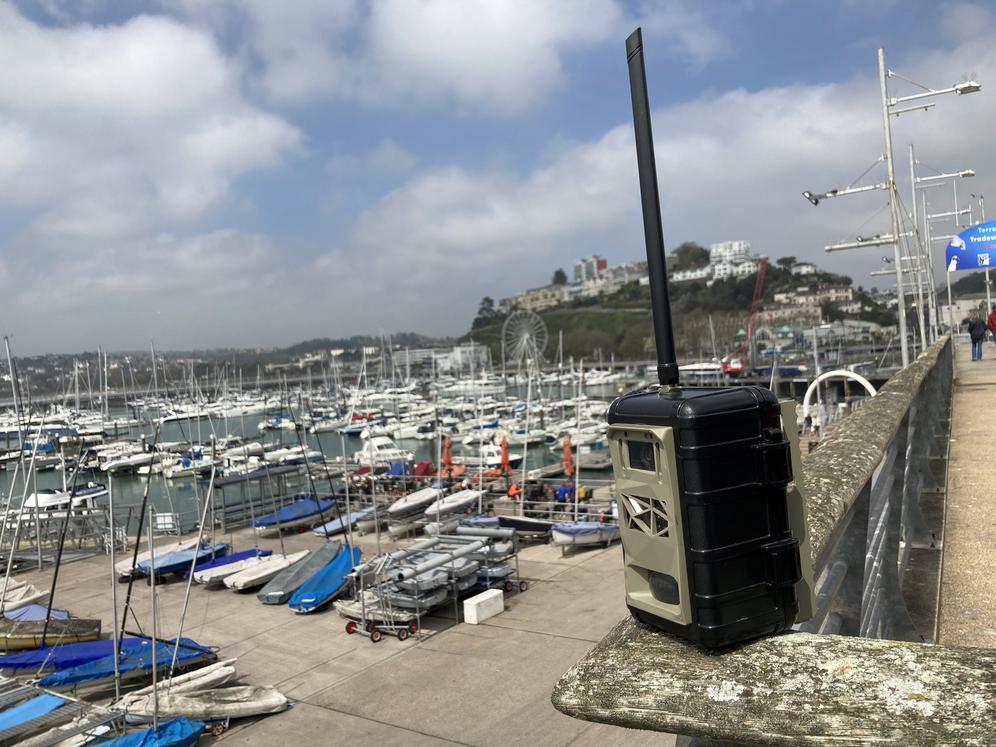
Two memorable occasions were a freezing cold day in December 2019 spent trudging up and down the dead-straight and flat canal path at Earith which showed our sensor endpoint could make connections and send data alerts 11 km using SF 12 (remember that Kate), and a test during the lockdown in early 2021 where a camera sent an image 6.8 km from Torquay to Brixham harbour.
However, we had never tested multiple cameras sending images to the Base Station all at once.
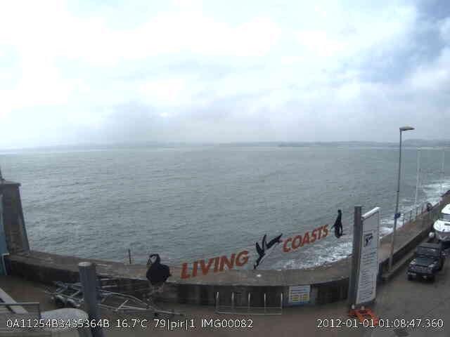
The image that dodged a thousand ship radios. Using Instant Detect 2.0's custom LoRa radio protocol a camera sent this image 6.8 km from Torquay to Brixham Harbour across a wide body of radio-frequency (RF) absorbing water. Credit: Sam Seccombe
The image transmission was achieved despite the electronic 'noise' from hundreds of boats and ships. Credit: Sam Seccombe
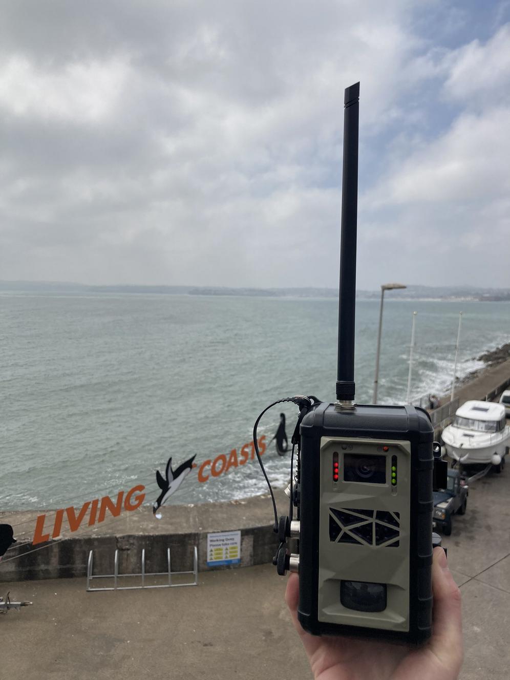
The camera at Torquay showing it's battery (red) and signal strength (green). Brixham Harbour is just about visible in the far distance. Credit: Sam Seccombe
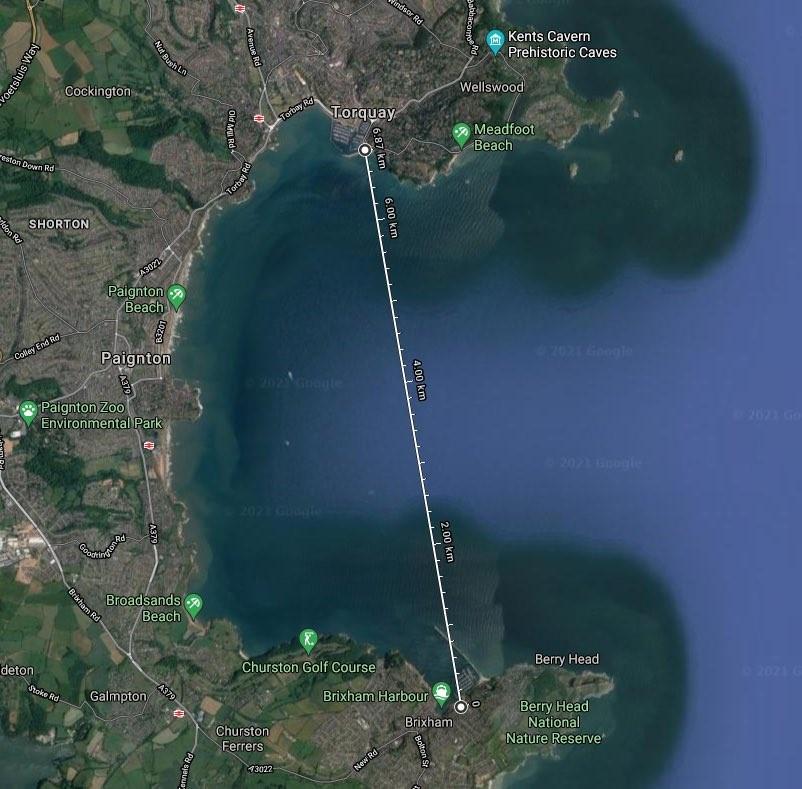
The 6.8 km transmission path of the image sent from Torquay to Brixham Harbour. Credit: Google Maps
Managing Multiple Cameras
We started our multiple camera testing at Whipsnade Zoo by ambitiously positioning 5 cameras as far away from the Base Station as possible. The cameras were set to take regular images on timelapse mode and field-of-view (FOV) check mode – this FOV check mode triggers the camera at a couple of set times a day – and as such, we would know exactly when and how many images they were capturing. This also meant that at certain times of the day the Base Station would have all 5 cameras trying to make a connection and transmit their images at once.
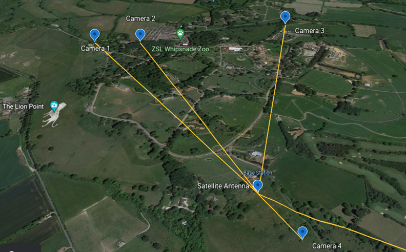
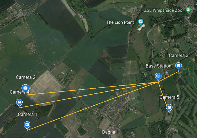
For the first deployment at Whipsnade Zoo we placed 5 cameras as far as possible from the Base Station. The yellow lines show the cameras' transmission paths. Not only would the cameras need to transmit through significant foliage, they would also be competing against the Zoo's high-powered radio network which is almost constantly busy. Credit: Google Earth
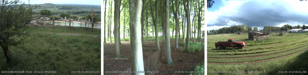
Image thumbnails sent by Cameras 1, 2 and 3 which were all over 1 km from the Base Station. Credit: Sam Seccombe
We had to be careful to ensure cameras would not capture images of the zoo-going public or be in locations that would make them difficult or dangerous to access - unfortunately this ruled out being inside most of the animal enclosures. Credit: Sam Seccombe
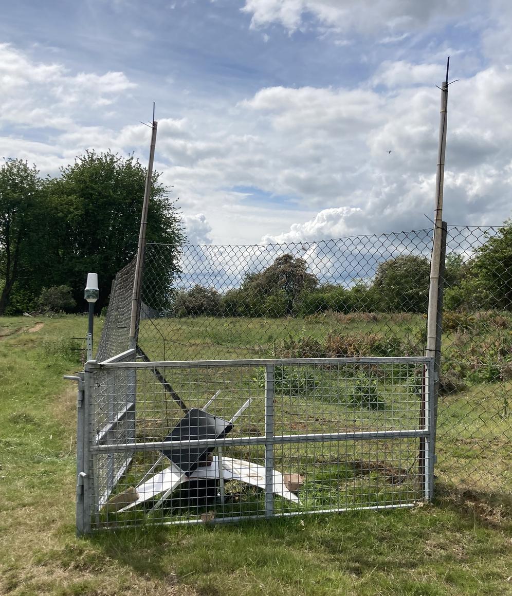
The Instant Detect 2.0 Base Station lived in a deer paddock at Whipsnade Zoo for 3 years. It even became visible on Google Earth. The LoRa radio antennas are raised up on bamboo poles, whilst the Iridium satellite antenna is the white upside-down ice cream cone. A 75W solar panel kept the battery charged. Credit: Sam Seccombe
On starting the test, we were pleased to find images regularly coming through from all the cameras, even the ones which had woods and buildings along their transmissions path. However, the time it was taking for images to arrive was extremely variable, with some images taking hours and even days to come through. It didn’t make much sense as there was no rhyme or reason to it.
How Many Devices Can Connect?
A common question I’m asked is how many devices can be used as part of a single Instant Detect 2.0 system?
This is a hard question to answer as it really depends on the deployment scenario. For instance, you could have a system with hundreds of devices that transmit very infrequently so that the Base Station is only ever receiving from one device at a time. Imagine a system spread across an empty desert.
Or, you could have a small system that is extremely active and transmitting frequently so that the Base Station must handle multiple transmissions simultaneously. Imagine a system deployed along a busy rainforest track.
The Theoretical Maximum
One way to answer this question is to look at the theoretical maximum.
Earlier, when I described transmission speeds (SF), I failed to mention that transmissions using different SFs do not interfere with each other, even when using the same frequency channel. This means that in theory, 6 devices could transmit on the 6 different SFs on the same frequency channel. Some would be transmitting very quickly, while others would be transmitting very slowly.
You might now be excited to learn that the Instant Detect 2.0 Base Station has a LoRa radio concentrator that can listen to 7 different frequency channels at once. This means that in theory, 6 cameras could be transmitting at 6 different SFs on each of these 7 frequency channels – so 42 cameras could be transmitting simultaneously!
Before we get too excited here, this would require a crazy amount of network co-ordination and most of the cameras using the slower SFs would have to stop before completing their image transmissions so as not to break the RF rules which limit transmission time.
Sorting Out The Chaos
To figure out what was happening to our image transmissions during our test, we had to intensively study and cross-examine all the cameras’ and Base Stations’ log files. For those not familiar with log files, they are text documents written by a device to record exactly what it is doing at any given moment. You can adjust what information is recorded in a log file to try and work out what is going on.
By checking the log files we were able to see which cameras were sending what images when on which channels. If that sentence was a headache to read imagine reading the actual log files! I’m extremely glad this phase of testing is over…
Aug 15 16:05:03 buildroot local4.debug bs_lora_process: TW3 pkt 167 FRAME_TRANSFER_DONE
Aug 15 16:05:03 buildroot local4.debug bs_lora_process: EVENT_UPLINK_CHECK generated at line 1452
Aug 15 16:05:03 buildroot local4.debug bs_lora_process: TW3 diff_pkt
Aug 15 16:05:03 buildroot local4.debug bs_lora_process: TW3 rx_close
Aug 15 16:05:03 buildroot local6.debug bs_uplink_process: POST 19372 of 29398
Aug 15 16:05:03 buildroot local4.err bs_lora_process: TW3 concludenocnf
Aug 15 16:05:03 buildroot local4.debug bs_lora_process: TW3 closing (was on channel 4)
Aug 15 16:05:05 buildroot local4.debug bs_lora_process: TW4 pri_end 0
Aug 15 16:05:05 buildroot local4.notice bs_lora_process: ZSLOAM: rssi|5|86.0
Aug 15 16:05:05 buildroot local4.debug bs_lora_process: TW4 pkt 3 linkcheckreq (from 3e251700, uuid a10214b3435364b)
Aug 15 16:05:05 buildroot local4.debug bs_lora_process: channelusage 254 254 3 254 5 254 254 254
Aug 15 16:05:05 buildroot local4.debug bs_lora_process: TW0 linkcfm cb in 357768
Aug 15 16:05:06 buildroot local6.debug bs_uplink_process: POST 20368 of 29398
Aug 15 16:05:10 buildroot local4.debug bs_lora_process: TW4 pri_end 0
Aug 15 16:05:10 buildroot local4.notice bs_lora_process: ZSLOAM: rssi|5|88.0
Aug 15 16:05:10 buildroot local4.debug bs_lora_process: TW4 pkt 4 linkcheckreq (from 3e251700, uuid a10214b3435364b)
Aug 15 16:05:10 buildroot local4.debug bs_lora_process: channelusage 254 254 3 254 5 254 254 254
Aug 15 16:05:10 buildroot local4.debug bs_lora_process: TW0 linkcfm cb in 357768
Aug 15 16:05:10 buildroot local6.debug bs_uplink_process: POST 21364 of 29398
Aug 15 16:05:13 buildroot local4.debug bs_lora_process: TW2 pri_end 0
Aug 15 16:05:13 buildroot local4.notice bs_lora_process: ZSLOAM: rssi|3|43.0
Aug 15 16:05:13 buildroot local4.debug bs_lora_process: TW2 rx_close
Aug 15 16:05:13 buildroot local4.debug bs_lora_process: TW2 startfilerx /media/sdcard/transfer/38062300/zsl00387.jpg of bytes 13720 from 0
Aug 15 16:05:14 buildroot local4.debug bs_lora_process: TW2 pri_end 0
Aug 15 16:05:14 buildroot local4.debug bs_lora_process: TW2 filerx 1, size now 244
Aug 15 16:05:14 buildroot local6.debug bs_uplink_process: POST 22360 of 29398
Here's a snippet of a log file from the Whipsnade Base Station. The Base Station is receiving images from multiple cameras (each 'TW' is a camera) while simultaneously transmitting an image to the cloud using its satellite connection (the 'POST'). It's also keeping track of which channels are in use ('channelusage'). Credit: Sam Seccombe
After running multiple tests, it became clear what was happening. A camera would connect to the Base Station and start transmitting using the fastest transmission speed – SF 7. Seconds later, another camera would join the same frequency channel.
If both cameras were using SF 7, then their transmissions would start interfering with each other. This interference would cause both cameras to automatically change to a slower more reliable transmission speed. This might see one camera using SF 8 and another using SF 9. This would result in images being sent far more slowly than they could have been.
This was especially infuriating to see when there would be other frequency channels unused and available. Our automatic transmission speed adaption logic was coming back to bite us…
Listen-Before-Talk
Fortunately, there was a relatively simple fix to multiple cameras trying to use the same frequency channel. It’s a polite spectrum radio technique called listen-before-talk. This is exactly what it sounds like and ensures that a camera will listen on a frequency channel for a few seconds to check if it is free before trying to transmit on it.
With listen-before-talk now active, we were starting to achieve really quick transmissions from multiple cameras at once, as each camera would use a different frequency channel to transmit at the fastest SF.
Channel Map
But what happens if there are more than 7 cameras trying to transmit, or if a camera has already used all their allotted RF time on a given frequency?
This is where things can get really complicated but the simple answers are:
1) Queue up cameras and make them call back when all frequency channels are already busy,
2) Dynamically keep track of which cameras have used what frequency for how long – we call this a channel map – and then intelligently manage what camera can hop to what channel when.
Self-Healing
Another issue a system might encounter in the field is for the Base Station to go offline. This could be caused by the Base Station battery running out or its antennas being attacked by animals (possible foreshadowing for the next Beta testing article)…
If this happens, we don't want our devices to use up all their battery power trying to constantly reconnect to the offline Base Station, but at the same time we don’t want our devices to just stop trying to connect as then we would have to visit every deployed device to restart the connection.
To achieve this, we developed a logic flow that would balance saving battery power while also re-establishing a connection.
This ‘self-healing’ proved itself time and time again during Alpha testing and it was particularly useful when some cameras were over 2 km away on a nearby farm. It gave me great satisfaction to replace a depleted Base Station battery after the Base Station had been offline for more than a week and see all my cameras reconnect within a 4 hour time frame.
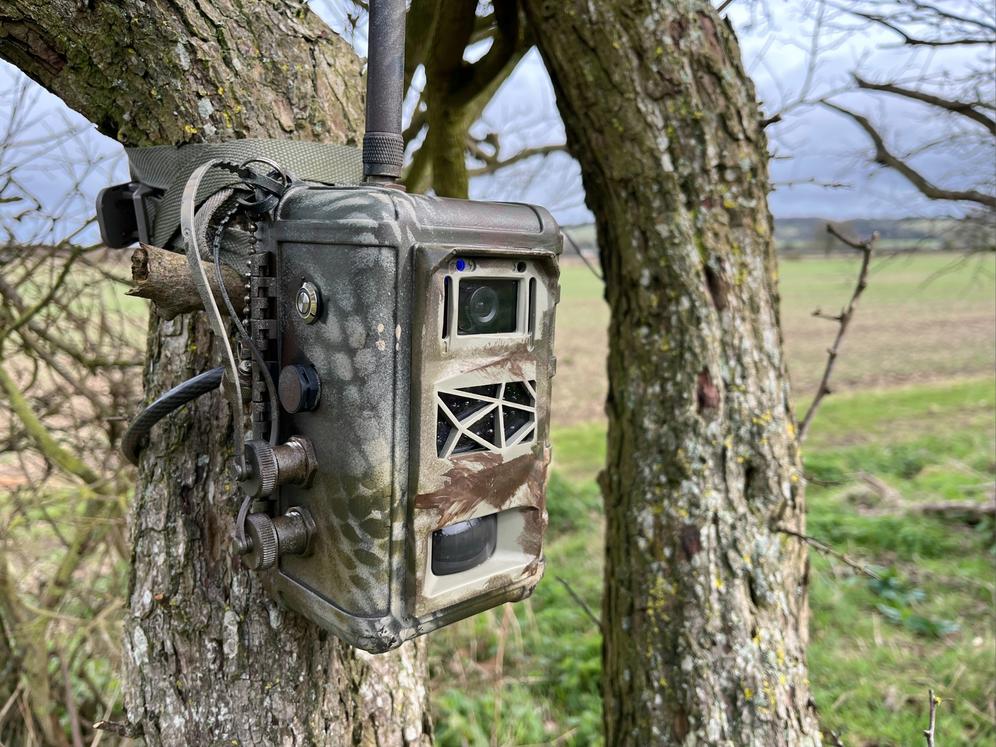
It was always such a relief to see cameras automatically re-connect to the Base Station when the Base Station had been offline for a while. The cameras deployed 'in-public' at Dagnall Farm were camouflaged with spray paint and locked to trees using python locks. Credit: Sam Seccombe
Network Wake/Sleep
The final thing to cover about Instant Detect 2.0’s custom LoRa radio network is the ability for the entire network to wake and sleep together. This is another unusual feature of the system and not something you would expect of a system with ‘Instant’ in its name.
A key design requirement of the Instant Detect 2.0 system is to be deployed in extremely remote landscapes where Base Stations will have to run entirely off battery power. As this will often require carrying the equipment in on foot, these batteries need to be portable so cannot be overly big and heavy.
While battery powered devices normally conserve power by going into low power modes when inactive, known as sleep states, most radio gateways will have their radio receiver powered on at all times so that they are always ready to receive things.
So how can a camera send an image to a sleeping Base Station?
The answer is simple, whilst being complex to achieve – time synchronisation. Every device on the custom LoRa radio network is tightly time synchronised with the Base Station and in doing so they can know exactly when the Base Station is scheduled to be awake and asleep.
The Base Station can now sleep for a minute or an hour and the devices will know when next to try and connect.
Camera-To-Cloud Testing
By May 2022, now on Revision 61 of the firmware, all of the above LoRa processes were optimised and we were ready for full camera-to-cloud testing. It was time to find the system’s limits.
One of our original technical design requirements was for a single Instant Detect 2.0 system to cover a wide area, with a target of 12.5 km2. To validate this with a real system, we needed cameras to be 2 km from the Base Station, but the Zoo just wasn’t big enough.
Fortunately, a Zoo neighbour at Dagnall Farm graciously agreed to host 3 of our 5 Alpha cameras in their hedgerows where they would be just over 2 km away. These cameras would end up becoming the main attraction during Instant Detect 2.0 demonstrations and spent over 2 years on the farm in sun, wind and snow.
For 2 years, three Instant Detect 2.0 cameras were deployed over 2 km from the Base Station in the hedgerows of Dagnall Farm. Credit: Google Earth
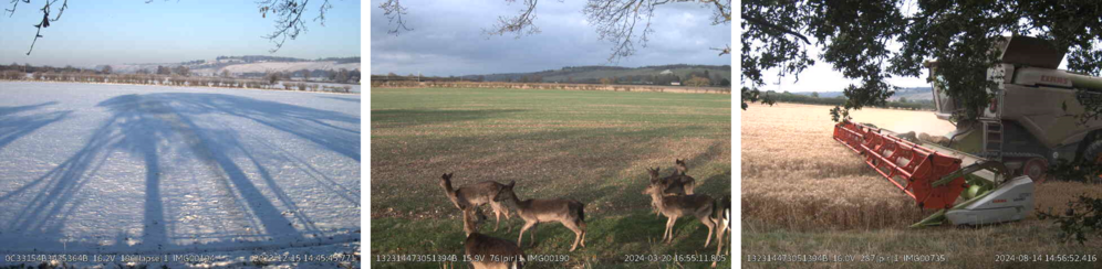
Through sun, wind and snow, cameras kept an eye on Dagnall Farm's fields. In the background you can just make out Whipsnade Zoo's White Lion which gives a sense of the system's coverage. These images were sent from Camera 4. Credit: Sam Seccombe
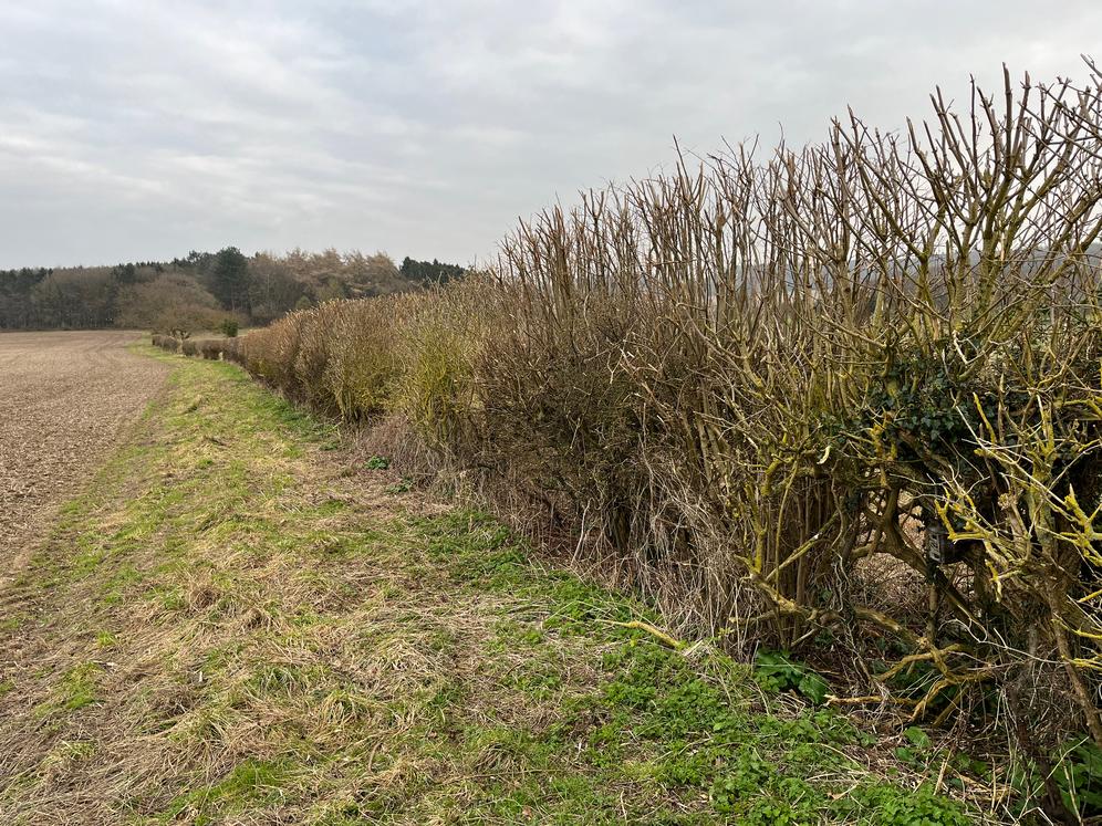
Can you spot camera 2 hiding in the hedgerow? Luckily no-one ever did. Twice it survived the annual hedge trimming. Credit: Sam Seccombe
Load Testing
With the system now running well, we wanted to know how many images it could send reliably and at what point would it all break down and get jammed up. We called this load testing.
Our first test had the 5 cameras each sending 24 images a day (1 an hour) so the Base Station would be handling 120 images a day. This was our targeted performance for image throughput. After two months, we were delighted to see that all 7,200 images had successfully been received at the cloud.
To see how far we could push it, for a week in September the cameras were set to capture 50 images a day (250 images for the whole system). Again, the Base Station handled it brilliantly and sent all 1,750 images back to the cloud.
Speed Testing
But how fast were images sending?
Our targeted performance for the speed of end-to-end transmissions was under 15 minutes. This is the time it takes for an image to transmit across the LoRa radio network, then for the Base Station to make a satellite connection and transmit it to the cloud.
To check these, we ran a test where the time of image capture and then arrival at the cloud would be recorded. While straightforward, this was incredibly time consuming. After the first wake/sleep test using batteries – more on this to follow – the transmission time was calculated for all 4,079 of the images.
The average transmission time was 6.5 minutes, with the fastest image taking just 3 minutes. 91.93% (3,750) of the images arrived in under 15 minutes, 4.9% (200) in under 20 minutes, and 1.89% (77) in under 25 minutes.
In total 99.9% of the images arrived in under an hour, with a single image taking 63 minutes when the satellite connection repeatedly failed to maintain a connection. I’m still annoyed at that image.
Power Durations
Another question I am frequently asked is, how long does the system run off batteries?
It depends on how big the batteries are. However, we did design the system to be portable and should therefore be able to be carried into a location on foot by a couple of normal people.
During all the previously mentioned testing, our Base Station had been powered using a 75W solar panel connected to a 12V lead acid battery, while our cameras used their internal lithium-ion batteries. These tests showed that our cameras would operate for around 100 days off batteries depending on how busy they were.
Our final system tests in 2023, now running Revision 64 of the firmware, were to see how long the Base Station could operate on battery. After some careful consideration we selected a 12V Lithium Iron Phosphate (LiFePO4) battery for the test, as we felt it provided the best balance between portability, weighing a just-about manageable 12.5 kg, while having a respectable 100Ah of power.
For our first test we ran the Base Station on a 5-minute sleep cycle. This meant it would be awake for 1 minute 30 seconds and then asleep for 3 minutes 30 seconds – or 30% awake and 70% asleep. It ran for 34 days, just under 5 weeks, receiving and sending 120 images a day. This was ok, but our target was 2 months.
With a 10-minute sleep cycle – 20% awake and 80% asleep - its duration increased to 45 days, and when on a 15-minute sleep cycle – 15% awake and 85% asleep - we got 54 days. It’s worth mentioning that for all these tests the Base Station was still receiving 120 images a day and transmitting them to the cloud, so it was likely awake a lot more than the schedule implied.
We were happy with these results and it’s also good to know for planning purposes.
Human Detection
Another world-leading innovation of the Instant Detect 2.0 system is the pairing of a low-power metal detecting sensor with a camera so that it will only capture images of human activity. This will enable the system to be used by wildlife rangers to detect poachers and other illegal logging and mining activity. This is different from all other camera traps on the market which use passive infra-red sensors (PIR) which trigger when they detect heat and motion.
To learn more about the development of this metal detecting sensor please see this previous article - Metal Detecting Sensors for Anti-Poaching.
To validate how well the metal triggered camera reduces false alerts (images captured that are empty or contain animals) a comparison test was run against a PIR camera. The test site was a field full of deer at Whipsnade Zoo that otherwise has no human activity.
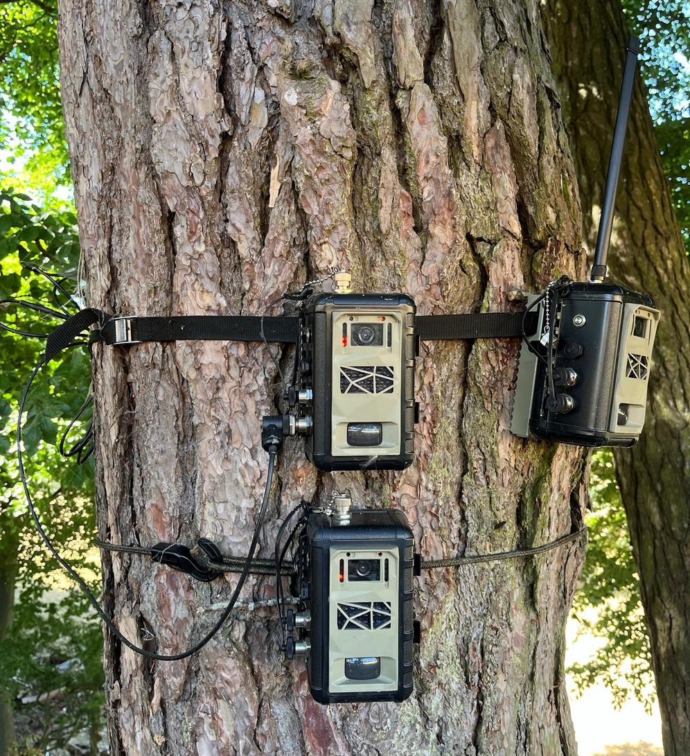
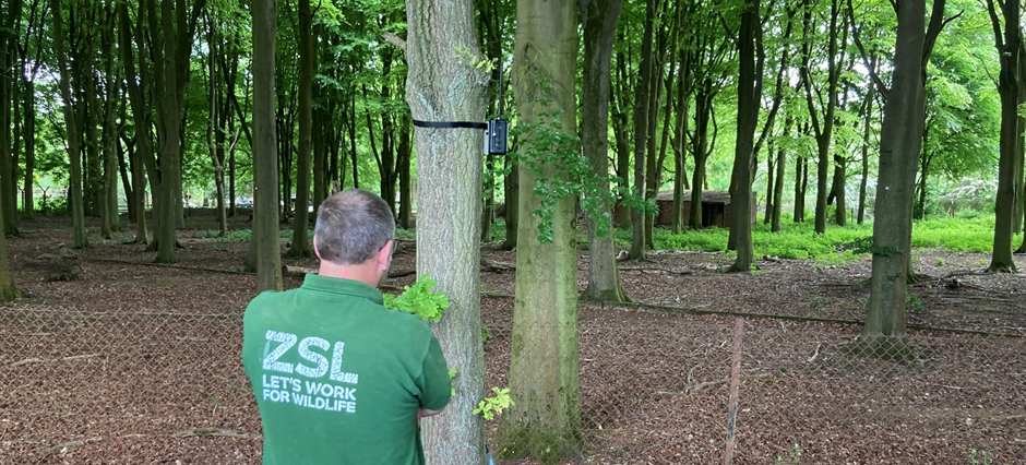
This tree in the corner of a deer paddock at Whipsnade Zoo was one of the busier testing sites. Here we can see a camera with an antenna taking part in load testing, and then two cameras on top of each other for the metal triggered camera (top) versus the PIR camera (bottom) comparison. Note the sensor cable connected to the side of the top camera. Credit: Sam Seccombe
Both cameras detected 100% of human activity. However, the PIR camera triggered 1044 times compared to 44 times by the metal triggered camera. This is a 96% reduction in image triggers.
1 in 5 triggers of the metal triggered camera was a human, with false triggers being caused during lightning storms and when deer stood directly on the sensor. In comparison only 1 in 50 triggers of the PIR camera was a human, with hundreds of false triggers caused by deer.
The metal triggered camera also ran for longer than the PIR camera, at 115 days compared to around 100 days for the PIR camera.
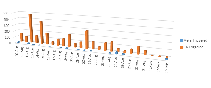
A visual representation of the difference in image triggers between the metal triggered camera in blue and the PIR camera in orange. Credit: Sam Seccombe
For more data analysis from this testing, please see the tweet below:
Illegal human activity in protected areas is causing irreversible biodiversity loss and habitat destruction, sometimes on an industrial scale. To stop this conservationists are using #Tech4Wildlife and #cameratraps. But how can a camera trap detect only human activity?🧵 1/ pic.twitter.com/VbIe3T0mJc
— SamSeccombe (@SamSeccombe) September 21, 2022
Other Bits And Bobs
As well as the above we also tested and optimised a variety of other things that I need to mention for completeness.
We had two iterations of an armoured camera security enclosure designed pro-bono by Cambridge Design Partnership which I thoroughly enjoyed testing to destruction. This security enclosure is designed to protect the camera from theft and animal damage when deployed overtly. Thanks CDP.
We also spent some not inconsiderable time optimising our Iridium satellite connections to handle connections being dropped mid-transmission, as well as developing dial-up logic for sub-optimum antenna placements where the signal strength is patchy.
With a new partner Icoteq Ltd’s support we also completely re-designed the camera’s IR flash board to make it 7 times more powerful than the original.
And once again, I must give an enormous thank you to Richard at Cool Jacket Coding Ltd for all of your incredible work developing the system’s firmware throughout this Alpha testing period.
Next Steps – Beta Testing
By May 2023, we were happy and confident with the system’s performance and had a good understanding of its limitations, so we set our sights on Beta testing and started building 10 new systems.
Beta testing would provide the final validation of the system with external users deploying Instant Detect 2.0 in a variety of climates for a variety of uses all over the world. To conclude this journey, a final article will be written later this year - Instant Detect 2.0’s Beta Testing.
Please also visit our website - Instant Detect 2.0.
Related content
Article
Instant Detect 2.0 emerges

Sam Seccombe
In the past six months Instant Detect 2.0 has physically emerged, with the first prototype systems built and ready for testing at the start of April. The ZSL team is now well into their optimisation and hardening phase...
3 September 2019
Article
Metal Detecting Sensors for Anti-Poaching
Sam Seccombe
Since 2016, ZSL’s Instant Detect team have been working on improving metal detecting sensors for anti-poaching. The team believe that using metal detecting sensors will provide a highly targeted detection of potential...
10 August 2020
Article
INSTANT DETECT 2.0 – THE OPTIMISATION YEARS
Sam Seccombe
The Zoological Society of London's Instant Detect 2.0 is the world's first affordable satellite connected camera trap system designed by conservationists, for conservationists. In this update, Sam Seccombe describes the...
21 January 2025
Add the first post in this thread.