


Hi everyone, I have recently started developing radio tags for wildlife. As you may know, they are quite expensive and I don't have that much capital. So I have spent some time learning how they work and searching the web for information.
And I found this in GiftHub. It works pretty well and I tested it and it works and I tried to make it as small as possible but I still have problems with the radio signal.
GitHub - schuele-embedded/150-MHz-Telemetry-Transmitter: 150 MHz Telemetry Transmitter for Wildlife Tracking
150 MHz Telemetry Transmitter for Wildlife Tracking - schuele-embedded/150-MHz-Telemetry-Transmitter

It is very sensitive to the environment or maybe it is the hot weather. Yes, I am in Thailand, haha. And this experiment is using MCU Attiny10 to control the signal. I tested it and it can work for more than 30 days using Idle Mode to save power at 1.8-2.5V. I think it should work well if we design the circuit well.
Since I don't have much knowledge about electricity, I use the sample circuit and add MCU. Now I'm going to add a power circuit for use with batteries with a voltage not exceeding 3V. And in the next step, I will modify it to be more accurate in signal and moisture proof in various conditions.
My requirements are:
- It must work at a frequency of 150-173 mhz.
- The battery can work for more than 3 months.
- And the spare parts are easy to find.
I will come back to update my development project soon. If you are interested, I can share the source code and other projects related to radio telemetry to track wildlife, including hawks. If you want to develop together, please contact me via email or Facebook. I am happy to share both the radio tag and the antenna construction material.
____________________________________________________________________________________________________________________________
I had time to assemble the parts that Mr. Steeman shared with me. His project is a radio telemetry for tracking hawks, which is not yet complete. I will update when it is complete.
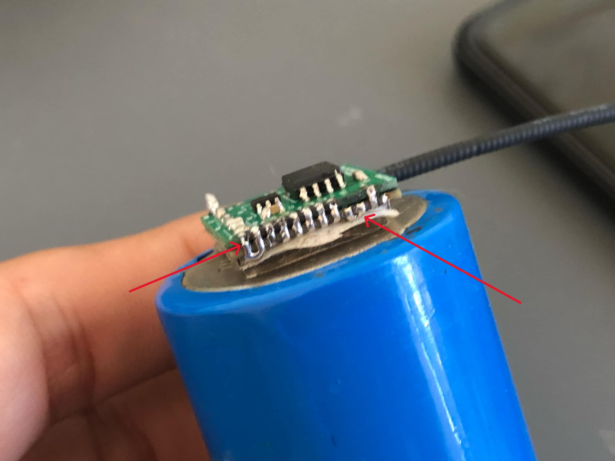
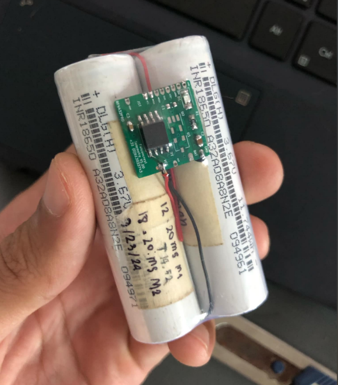
I tested it and it worked for about 2 weeks, I had it send a signal every 1 second. It runs on a 18650 battery with a capacity of about 800 mah.
And it's very small in size. It's big but the battery you need, I'm studying the code to see if there's a way that the house can reduce the energy consumption so that we can use smaller battery cells.
I tested two things: one was to connect the board and module together for easy customization, but it didn't have much effect.
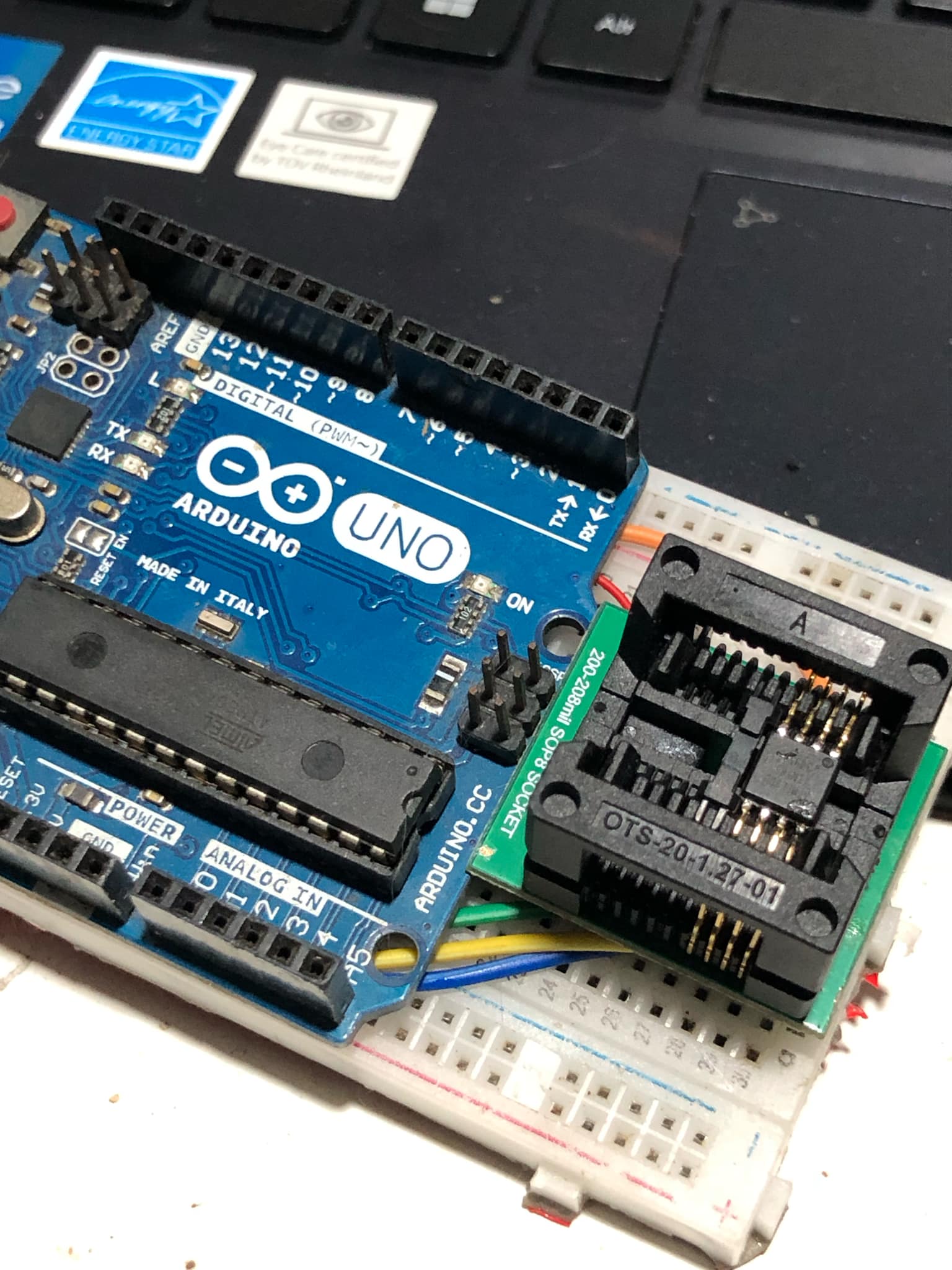
We can use Arduino as a program to upload. I got it when I was in high school and it still works fine to this day.

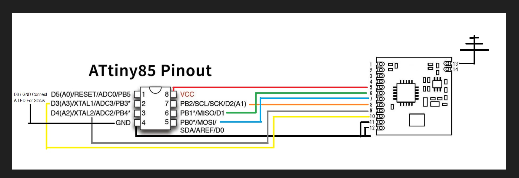
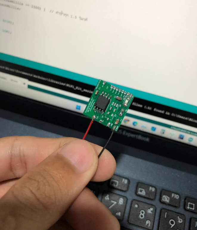
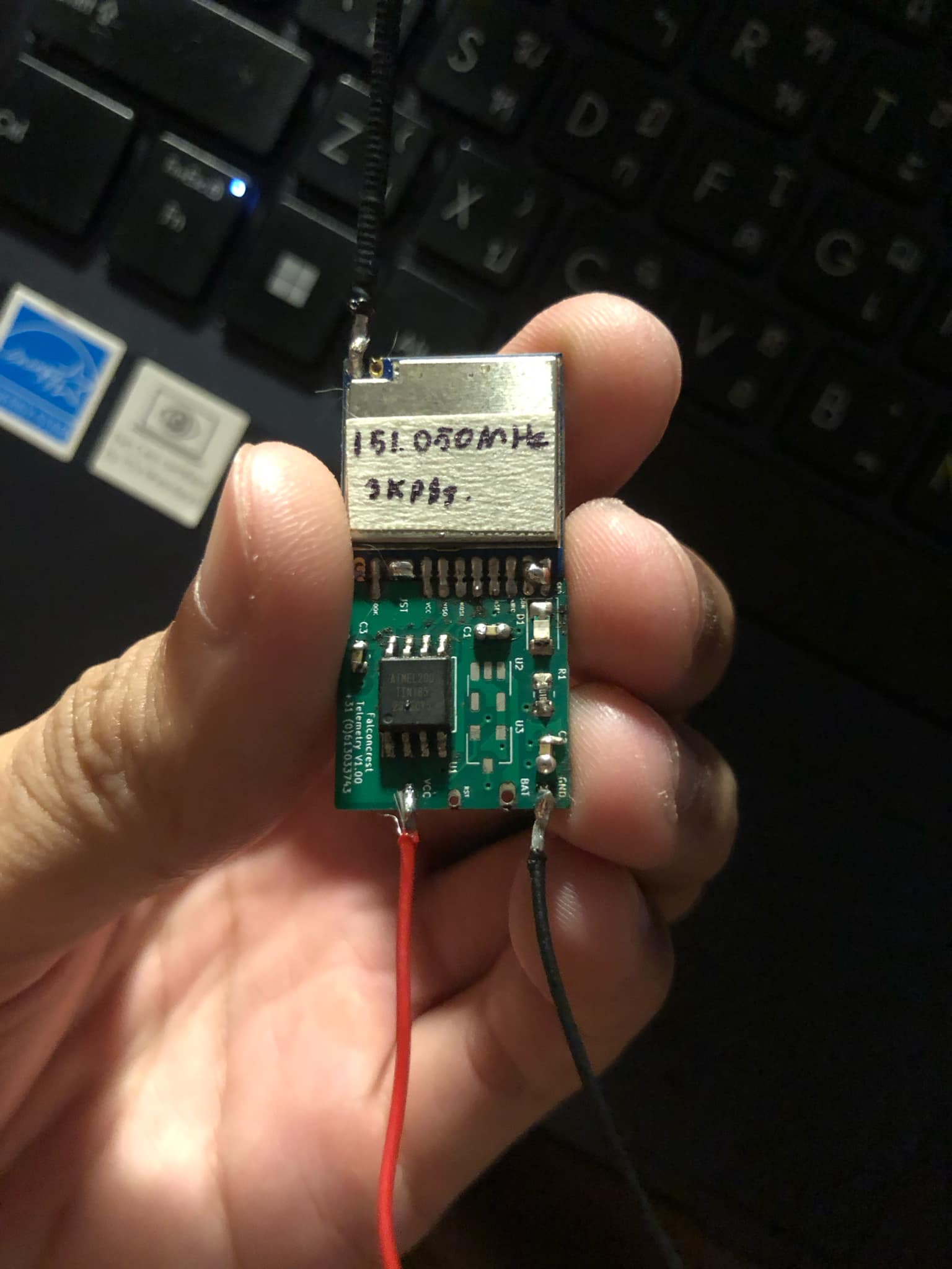
You can see the different sizes of both transmitters and yes they are very light. I chose to use a programmable radio module SI4463 and the controller is a very cheap Attiny85 but expensive for me because of shipping costs.
The antenna I use is fishing sling. You will be surprised how durable and strong it is. As long as you connect it tightly to the module and keep it protected from moisture, it will still work and the VSWR is very good.
I will be back to update again soon. Thank you very much for reading. I will be back as soon as possible.
Latest update_______28/11/2024_____________________________________________________________________________________________
For this update, I will be adding more details on the creation and details of the devices and their programming.
material
Software for radio programming
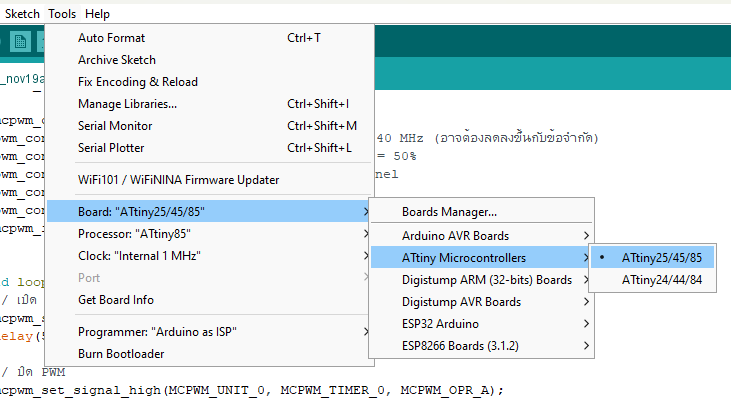
"""""Selecting a board for Attiny85 to use in your work"""""
To upload the working code for Attiny85, use ArduinoISP or if you have an upload tool, you can use it as you prefer. If you don't have one, you can follow this video
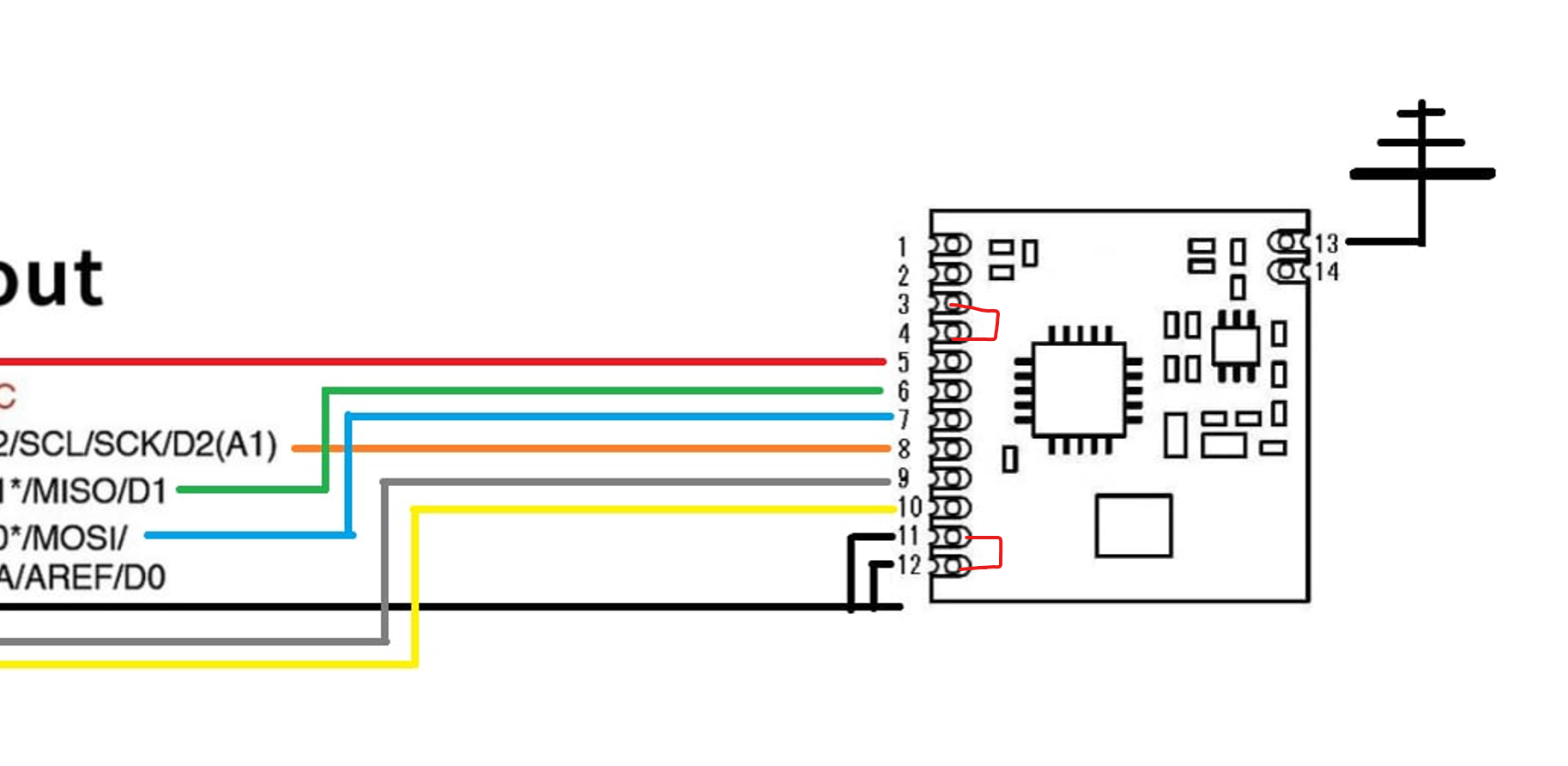
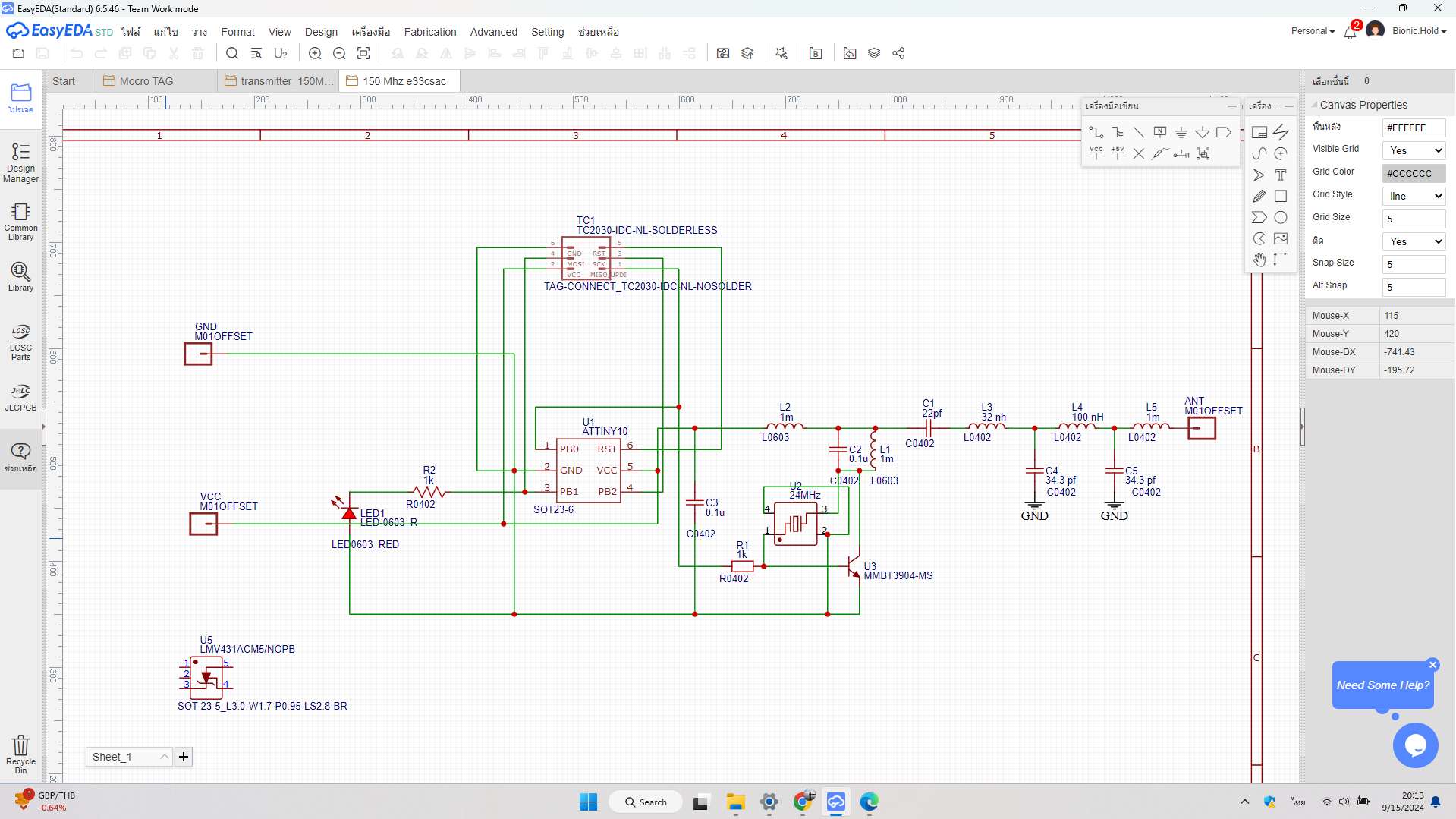
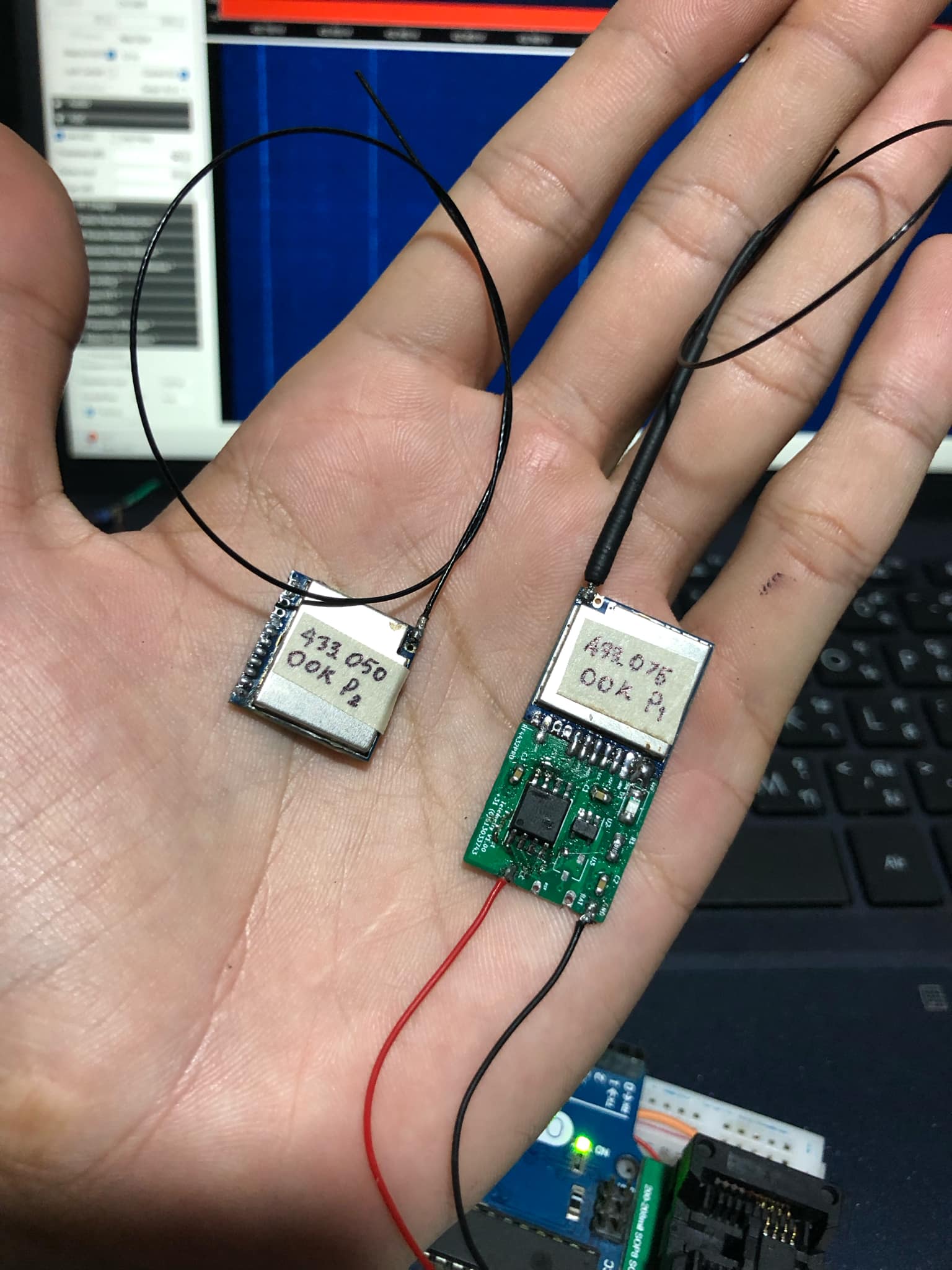
For using a frequency other than the default 433.100 MHz from the factory, it is necessary to solder specific pins on the SI4463. Connect Pin 3 and Pin 4 together, and also connect Pin 11 and Pin 12 together. This adjustment allows the device to operate correctly.
I am not entirely certain about this solution, but using this method has enabled the device to function. The frequency I am using is VHF 151.xx MHz.
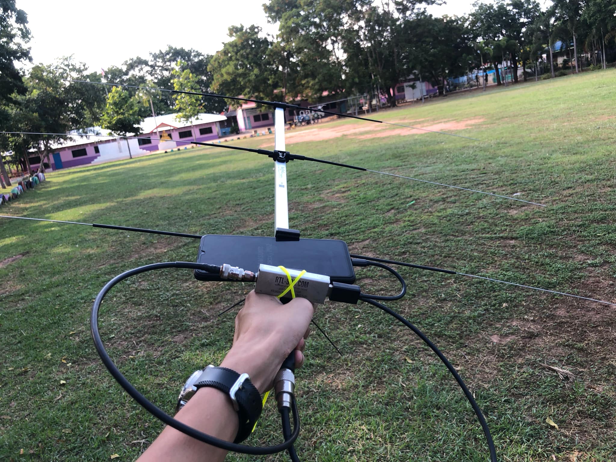
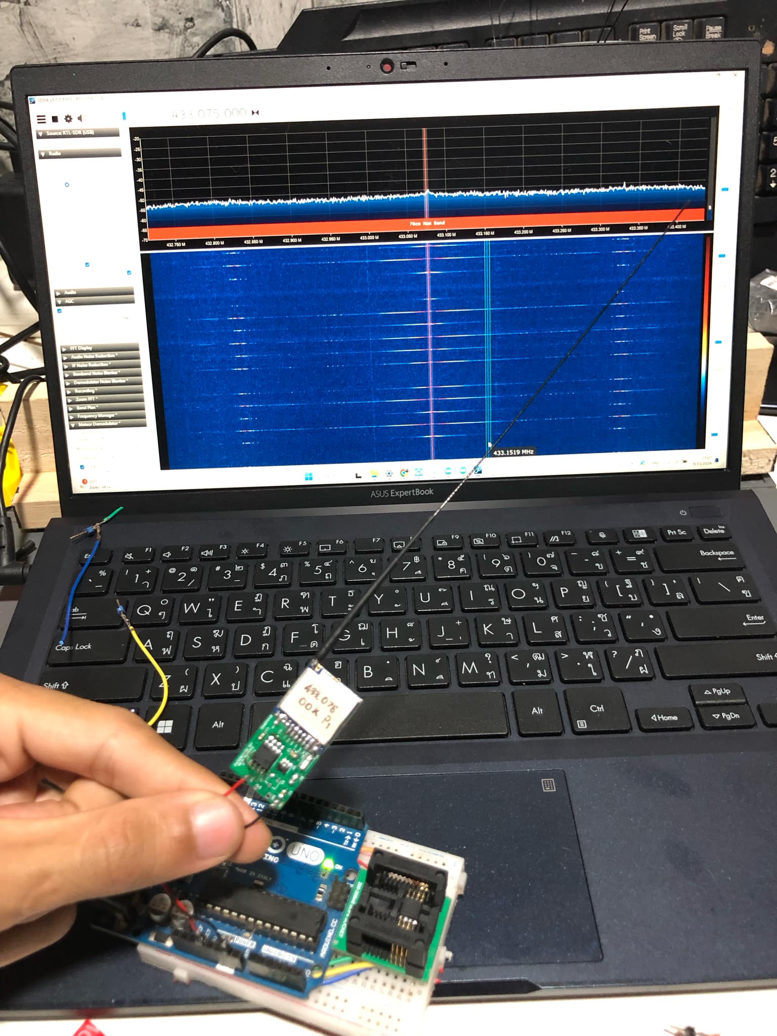
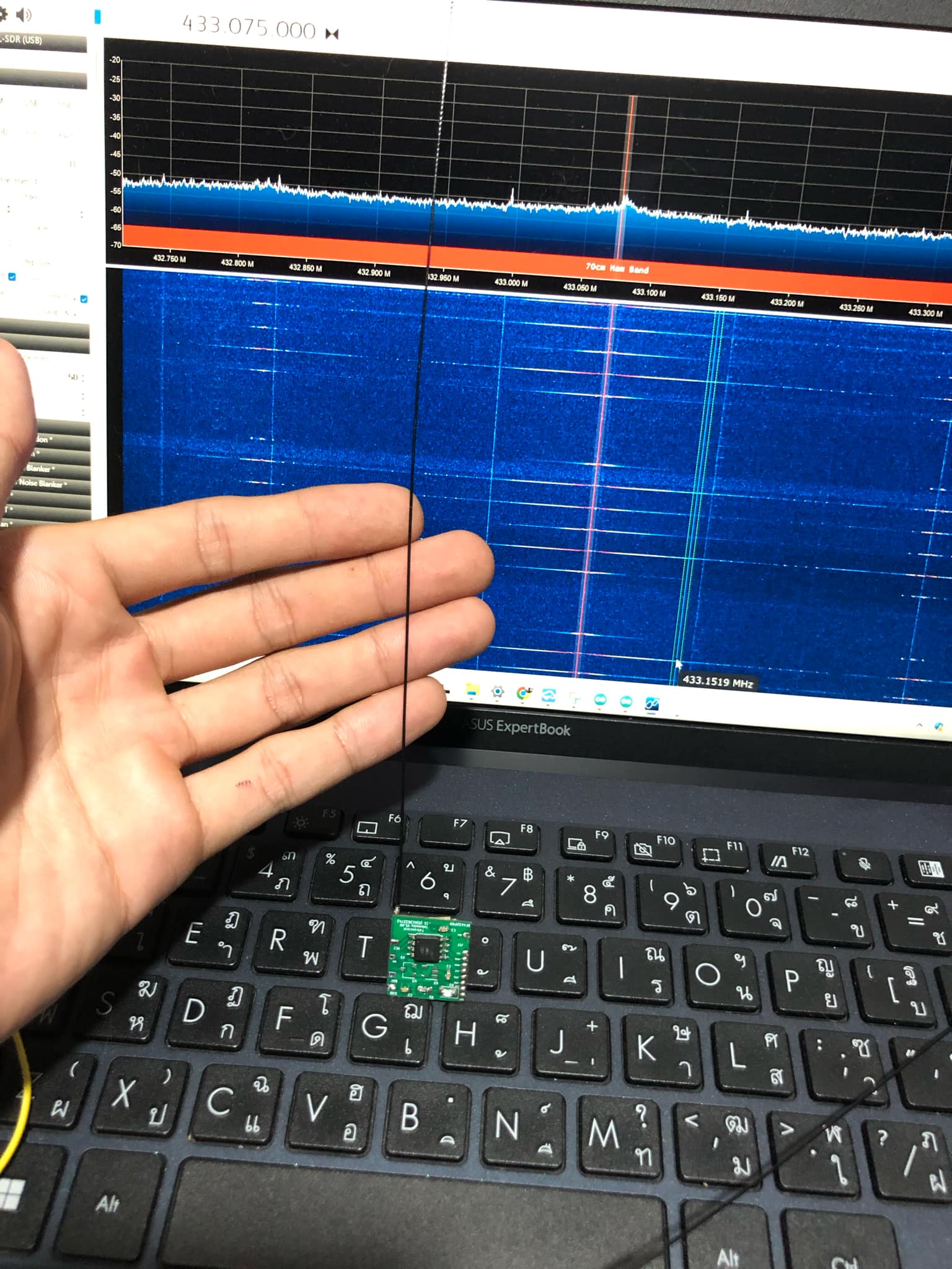
This is my test conducted with an SDR (Software-Defined Radio), which I connected to a smartphone using the SDR++ software as the receiver. I used an antenna that I built myself, and you can create one as well. The process is straightforward and easy to follow.
In my test, I achieved a range of over 1.2 kilometers after improving the antenna to enhance its efficiency.
If there are any errors in all of this, I sincerely apologize.
contact us
email bionic.Hold@gmail.com
Fb https://www.facebook.com/BioncHold
18 September 2024 5:54am

I don't have much free time today because it's going to rain and yes I tested the tracker. It works fine with my SDR and my old phone. Don't laugh at me because I only have this one. LOL
I have tested it in my garden and open area on my farm. It works very well at 800 meters. That's all I have tested and will update again when it is done. Since some of my spare parts are not available in my country, I tested as you see. I think it should work well with the Hawk modulator receiver.


23 September 2024 5:36pm
Hi Since I haven't been able to test the tracking device lately due to the storm that has kept me from going out, I've been testing the Attiny85 in Power Down mode to test its continuous operation with readily available batteries. This is part of my project.
My requirement was long battery life for a VHF/UHF collar I was testing to create a cheap tag. A big question was how long it would last, so I simulated the tag with two working modes: normal tracking and constant. The tag works by sending a PWM signal through an LED, which I have tested allows us to control the signal instead of RC.
You may want to add other detections, for now I'm using a 1 MHz CPU Attiny85 as it's not really needed, the lowest speed is the solution, and I'm using a very inexpensive SI4463 radio module as a transmitter. A 3V battery cell is enough to transmit every 2 seconds for 12 days with enough power, and this is a simple wiring diagram.
The cost is not too expensive, probably not more than 15 uSD, and we can set the frequency a lot, including setting the iD. I think this is a good prototype. I am improving the code and the example circuit board to make it easier to build for those who are interested but do not have the tools, just need a little electrical skills. I will come back to update again if I can go test after the storm, haha. For the small telemeter, I also plan to use a smaller MCU, just need to design the circuit less complicated. Since I do not have the example tag, please understand me.
13 October 2024 1:12pm
Hello everyone, I’ve had a few days off as I was dealing with some personal matters. Today, I’m here to update you on my project. I’ve tested several things and found that we can configure the signal frequency we need. However, I’m not sure if it will be compatible with all receiver models. I only know that the module allows various modulation settings, as shown in the image.
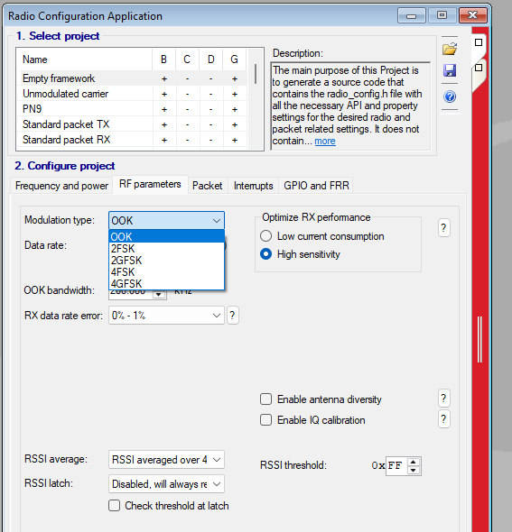
You can see that there are many options available, and I’ve chosen to use OOK modulation only because I’m testing it with an SDR, and it works well. The issues I’ve encountered are mainly with some parts that I can’t find replacements for and the SDR not performing as well as expected. As I mentioned, the SI4463 can be programmed to operate within a frequency range of 140-1050 MHz, but the module is set to 433 MHz by default from the factory. You can adjust it for your specific needs, but I’m still facing some ongoing and upcoming issues.
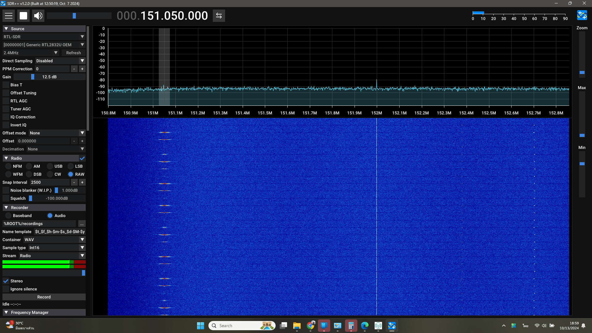
This is a test using SDR. I’ve checked, and although it works well, there’s an issue with harmonics in the signal, which I think could be a significant drawback as it might cause confusion. I’ll work on fixing this to improve performance.
I want to thank the group members who sent me a sample Perdix VHF tag for testing and comparison. I’m very grateful! An important note is that the tag operates at a very low voltage, only 3-3.3V! Exceeding this could damage the module. While the ATTiny85 can handle higher voltages, the SI4463 cannot, so be cautious about this. I’ll update everyone again soon and hope you’re enjoying your experiments. Please let me know if you find any issues, as I’m always open to feedback—I don’t know everything in this field. Thank you!
14 October 2024 3:40am
I don't know the specific module you're using but I've seen many small radio modules use a notch filter for the 2nd harmonic and a low-pass filter for higher harmonics. This means that as soon as you tune to a different band the notch filter will not do what it's intended to do and the low-pass filter's corner frequency will be too high or too low.
Chittakon Amonsin